Keywords
Thermal ablation; Tumor; Thermal diffusion; Radiotherapy; FEM
Introduction
A long time ago, humans knew that the temperature of the body can be used as an important sign to assess the health of people. The first physicians used their hands to estimate the temperature of patients in order to diagnose illness. This method can only be applied to detect the temperature abnormalities in the surface of the skin. The deep temperature of the tissue cannot be assessed. Nowadays, many devices and methods are developed [1]. The thermometry designers offer many extremely sensitive devices built with different technologies. Also, the thermal imaging techniques, such as Magnetic Resonance Image (MRI), and Infra-Red (IR) Image, are usually used in biomedical applications and surgery. It plays a double role: imaging and temperature measurements [2]. All these techniques offer a thermal measurement of the body temperature, which is very important for physicians to identify the painful area and deduce the physiological and pathological state of the body. For example, an insect bite is generally associated with higher local temperature. Successful use of the thermal information, including temperature and heat flux at the skin, in clinical diagnosis of many diseases has been proved [2-4]. With all the technological innovations and the large understanding of the human physiology, the thermography is still an attractive technique because of its advantages like being utterly harmless, highly sensitive and economical.
We can also use the thermal techniques for treating some diseases. In fact, the thermal ablation therapies, such as a Radio Frequency (RF), microwave, and cryo-ablation, offer minimally invasive solutions for local treatment of different kind of tumors [5-7]. The non-invasive thermal method of treating cancer tumors is especially suitable for elderly and people who do not support surgery. This non-invasive therapy could avoid infections, reduce recovery time, and possibly also reduce costs [8]. Nowadays, the thermal therapies are one of the most used methods for treating cancer. They consist of using thermal sources to destroy the malignant cells and protecting the surrounding healthy cells. To completely achieve the destruction of the tumor with minimal damage to the safe tissue, it is important to have a mathematical model that simulates the temperature distribution over the tissue. The distribution of the temperature in the living tissue is described by Pennes’ equation [9].
 (1)
(1)
Where ρ, c and k are, respectively, the density (kg/m3), the specific heat (J/kg·K), and the thermal conductivity (W/m·K) of the tissue. T is the local tissue temperature (K) and Ta the arterial blood temperature (K). ρb and cb are the density and specific heat of the blood, respectively. The perfusion rate is represented by ω (l/s). Qm is the metabolic heat production per volume (W/m3). J stands for the current density (A/m) and E for the electric field intensity (V/m).
The left hand side of Equation 1 refers to the storage energy. The first term on the right hand side represents the energy diffusion within the tissue; the second term describes the temperature exchange between the blood and the surrounding tissue, due to blood convection. The last term J.E captures the Joule Effect, it represents the external deposited energy [10]. In the absence of an external heat source, the Joule effect in our case, Equation (1) describes the Pennes equation modeling the Bio Heat Transfer (BHT) in biological tissue without external excitation.
Since the landmark paper by Pennes, in 1948, many researchers studied the BHT in human tissue [11]. Many models have been proposed to remedy the shortcomings of the Pennes model [11-14]. Even though this model was criticized and many other models have been developed since, Pennes’ model is still efficient [14-20].
The solution of the BHT Equation (1) is widely explored and investigated. The conventional numerical methods appear inefficient, since the temperatures for the whole region must be solved simultaneously. Also the complexity of the geometry and the properties of the tissue makes the analysis hard and complicated [21]. So, different approaches to solve the BHT equation were implemented such as Finite Element Method (FEM), Finite Volume Method (FVM), and Finite Difference Method (FDM) [22,23] or Monte Carlo methods [21].
Supan et al. [24] simulated an RF hepatic ablation with 3D-FEM method. They developed a 3D model with 4 electrodes based on thermo-electrical module. They showed how the blood vessel proximity to the tumor affects the temperature by Joule effects and blood convection. By the year 2013, Ruxsapong et al. [25] developed a 3D FEM method for RF ablation in asthma therapy. They designed a probe with ellipse shape to rise the airway wall dimension. They used a 380 kHz RF probe at 65-75°C for 10 seconds to heat the airway wall. In 2012, Yhamyindee et al. [26] modeled a micro wave ablation of hepatic cancer using the 3D FEM method. They analyzed two models, one with artery and the second without artery. They explored the effects of blood perfusion rate and the coagulation area. In 2015, Stefaan et al. [27] built a bipolar 2×2 electrodes model and used the FEM method to simulate the model. They focused on the effects of the electrode diameter and the duration of the process. An experiment with an ex-vivo bovine liver was conducted. Kok et al. [28] showed the development of the software tools for real time controlling of Hyperthermia treatment planning (HTT). They investigated the different steps from tissue segmentation and electromagnetic calculation, to thermal modeling and phase/amplitude optimization. The direction of the temperature diffusion was not explored. Some researchers investigated the control of the injected dose, and others explored different architectures of the probe. Our model is based on the control of the direction of the temperature diffusion during the treatment. For a better appreciation by the reader, we have summarized in Table 1 the relevant information related to the different models using 3D FEM for thermal ablation.
| Research |
Method |
Applied for |
Probe |
Injected power |
| Supan et al. [24] |
RF ablation |
hepatic ablation |
4 electrodes |
16W |
| Ruxsapong et al. [25] |
RF ablation |
Asthma therapy |
Ellipse shape |
22 V for 10 s |
| Yhamyindee et al. [26] |
Micro wave |
Hepatic cancer |
Electromagnetic wave 2.5 GHz |
50 W for 10 s |
| Stefaan et al. [27] |
RF ablation |
Ex vivo bovine liver |
Bipolar 2×2 electrodes |
50 W |
| Kok et al. [28] |
Software tool for controlling treatment |
real time controlling of Hyperthermia treatment planning (HTT) |
---- |
Increasing the tumor temperature to 40–45°C |
Table 1: 3D finite element method for thermal ablation.
Successful hyperthermia treatment of tumors requires understanding the thermal processes in both dead and healthy tissues. Also it is important to have the control of the deposited energy by manipulating the amplitude and the time of each pulse to control the heat diffusion in the tissue. Other parameters can be introduced to control the temperature distribution. The external heat source and the heat transfer coefficient are two important parameters. Controlling these parameters gives us a chance to reduce the damage to the tissue surrounding the tumor during a cancer therapy, and to achieve a safe and effective treatment. To accomplish this goal, an estimation method of these parameters was explored by Araseh, et al. [29,30].
Successful hyperthermia treatment of tumors requires understanding the thermal processes in both dead and healthy tissues. Also it is important to have the control of the deposited energy by manipulating the amplitude and the time of each pulse to control the heat diffusion in the tissue. Other parameters can be introduced to control the temperature distribution. The external heat source and the heat transfer coefficient are two important parameters. Controlling these parameters gives us a chance to reduce the damage to the tissue surrounding the tumor during a cancer therapy, and to achieve a safe and effective treatment. To accomplish this goal, an estimation method of these parameters was explored by Araseh, et al. [30]
The objective of the thermal therapy being the destruction of the malignant cells, it is important to study the malignant cells destruction process due to the injected heat [30,31]. Many researchers have investigated the tissue damage during thermal therapy [32-35]. The damage can be calculated based on the Arrhenius equation given by:
 (2)
(2)
where ξ is the pre-exponential factor (s-1), R is the universal gas constant, 8.314 (J/(mol·K)), Ea is the activation energy to start killing cells (J/mol), and T is the temperature (K). The thermal damage relationship, described in Equation (2), depends on temperature and time. So, if the duration of the pulse is long, the tissue damage can happen even for temperatures as low as 43°C [33,35].
Based on the BHT Equation (1) and the tissue damage Equation (2), we aim in this work to develop a 3D model for thermos-ablation tumor, and to simulate the process using COMSOL Multiphysics which is a FEM analysis, simulation and solver software. It is based primarily on the FEM and partially of the FDM for some module [36-38]. The most important contribution in this work is the control of the direction of temperature diffusion in the tissue during the treatment by manipulating the cathode direction. We proposed a directional probe with curved cathode to ablate the malignant cells. This curved cathode is used as a directional heater. The purpose of controlling the direction of temperature diffusion in living tissues is to save the surrounding healthy cells. Others methods exist in literature for hyperthermia therapy without overheating the surrounding living tissue, like adding a cooling source to reduce the temperature [39]. Hyperthermia can be used with other techniques, like chemotherapy and radiotherapy. The rest of the paper is organized as follows. Section 2 gives a description of the used methods and materials; and presents the heating process. The results are reported in Section 3. Section 4 summarizes the main work and concludes this paper.
Materials and Methods
The heating process
The purpose of the heating process is to kill the malignant cells with less collateral damage in the surrounding healthy tissue. A big challenge of this process is to find a new method to control the heat diffusion. To solve this challenge, researchers explored two elements. The first one is the control of the deposited energy [31,32] by controlling the heating source. The second one is the control of the direction of the heat diffusion. In this work, we mixed both methods by controlling the heat source and the direction of the temperature diffusion. We proceed as follows: the probe is positioned in the center of the tumor and a succession of power pulses are sent for a duration of 2.5 s with an amplitude of 2 Watts. After each power deposition, we check the necrotic rate. If the cells are predicted to be dead, we move the probe to the new position and we add one more pulse to kill all the local malignant cells. To ensure that all the malignant cells are predicted to be killed at the limit of the tumor with a minimum of healthy cells dead, we propose the injection of one additional pulse and check the necrotic rate after the relaxation time. If the cells are predicted to be killed, we move the probe, otherwise we continue the injection of additional pulses. The heat source used is a succession of pulses. Figure 1 shows the form of the heat source.
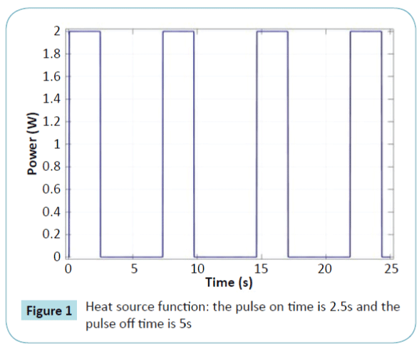
Figure 1: Heat source function: the pulse on time is 2.5s and the pulse off time is 5s
Figure 2 presents the diagram of the different steps of the heating process proposed in our model. We start the ablation at the centre of the tumor. Once the targeted cells are ablated, we move the probe to a new position, and so on, until the whole tumor is removed. The number of cycles depends on the volume of the tumor. We stop the process once the whole tumor is killed.
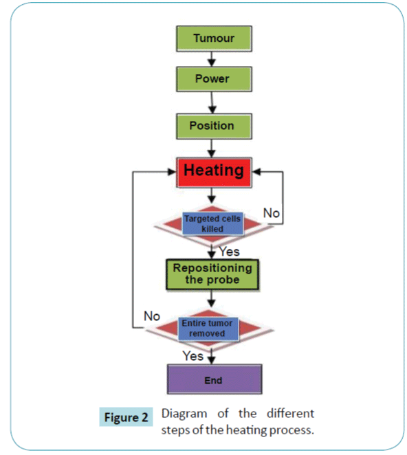
Figure 2: Diagram of the different steps of the heating process.
The probe architecture
Our probe is designed to be used as a directional heater. In contrast to many other models [24,25,27], our probeuses one curved cathode. The main reason for the curved form is to give a direction to the heat diffusion. Figure 3 shows the electrode with a curved form. The radius of the cathode is 0.9 mm. The revolve angle is 180?. The distance between the two centers of the extremities of the cathode is estimated at 16 mm.
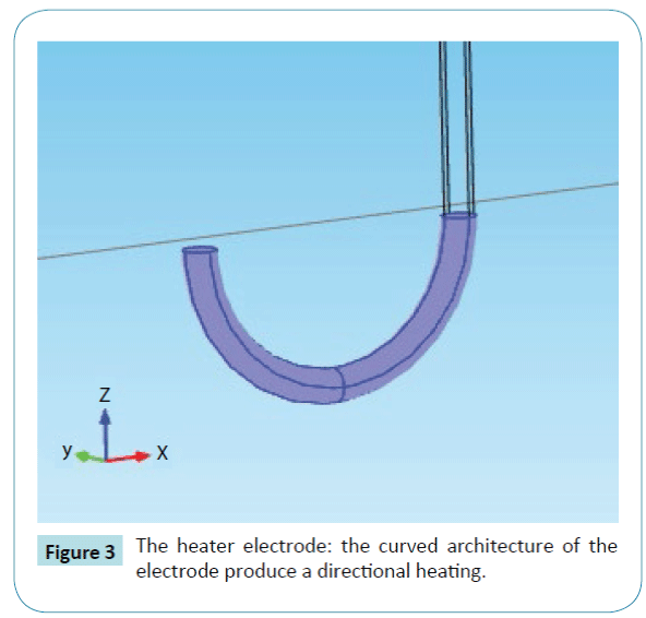
Figure 3: The heater electrode: the curved architecture of the electrode produce a directional heating.
The entire architecture is reported in Figure 4. We proposed a cylinder form. The probe is applied to remove a supposed tumor.
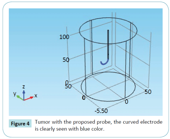
Figure 4: Tumor with the proposed probe, the curved electrode is clearly seen with blue color.
Material properties and thermal boundary conditions
Table 2 summarizes the different values of the basic blood parameters [24,36] and Table 3 shows the liver, the electrode and the trocar base parameters inspired by literature [24,34,36]. The initial value of the tissue temperature is 310.15 K (37°C). As thermal boundary conditions, we used open boundaries all along the tissue so the heat can flow out of the tissue naturally (Cauchy-Neumann boundary conditions type).
| Blood parameters |
Name |
Value |
| Heat capacity |
cb |
4180.0 J/(kg·K) |
| Density |
rb |
1000.0 kg/m3 |
| perfusion rate |
ω |
0.0064000 l/s |
| Arterial blood temperature |
Ta |
310.15 K |
| Initial temperature |
T0 |
310.15 K |
Table 2: Values of the basic blood parameters [24,36]
| Name |
Unit |
liver |
electrode |
Trocar base |
| Heat capacity at constant pressure , cb |
J/(kg·K) |
3540 |
840 |
1045 |
| Density, ρ |
kg/m3 |
1079 |
6450 |
70 |
| Thermal conductivity, k |
W/(m·K) |
0.52 |
18 |
0.00001 |
| Electrical conductivity, σ |
S/m |
0.333 |
0.00000001 |
0.026 |
| Frequency factor, ξ |
1/s |
7.39·1039 |
-- |
-- |
| Activation energy, Ea |
J/mol |
2.577·105 |
-- |
-- |
Table 3: Thermal and electrical properties of the 3D FEM model inspired by literature [24,34,36].
Results
A 3D liver tumor removal model is simulated using COMSOL Multiphysics and the results are reported. The Joule Effect is used to heat the targeted tissue using a curved cathode as a directional heater. The necrotic tissue and the temperature are reported.
Figure 5 shows the mesh of the targeted tissue realized by COMSOL. The solution is found at each element of the mesh. The entire geometry is divided into 16164 elements. The smallest element quality is 0.2224 and the average element quality is 0.7233. The mesh is smaller near the electrode, and larger near the boundary
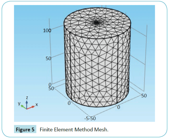
Figure 5: Finite Element Method Mesh.
Figure 6 shows the surface temperature distribution of the tissue after 25 seconds heating. The effect of the curved cathode is clearly seen. The temperature increased in the cathode direction without an important thermal perturbation in the surrounding tissue.
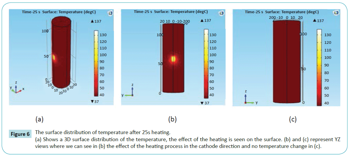
Figure 6: The surface distribution of temperature after 25s heating.
(a) Shows a 3D surface distribution of the temperature, the effect of the heating is seen on the surface. (b) and (c) represent YZ views where we can see in (b) the effect of the heating process in the cathode direction and no temperature change in (c).
Figure 7 shows the influence of the curved electrode. It produces a directional heating. It removes just the targeted cells near to the curved cathode. It keeps safe all the surrounding tissue.
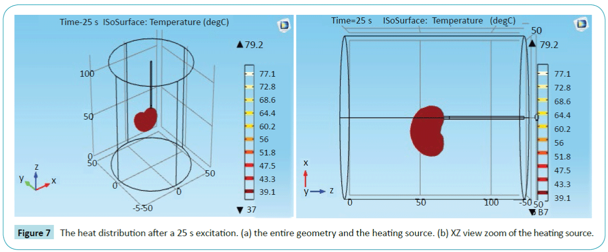
Figure 7: The heat distribution after a 25 s excitation. (a) the entire geometry and the heating source. (b) XZ view zoom of the heating source.
To better understand the effect of the heating process, we evaluated the necrotic tissue at 4 different points to visualize the necrosis phenomenon. The first point is adjacent to the cathode heater (the blue color), and the last one is on the exterior boundary (the magenta color). The results are reported in Figure 8 It is important to mention that the tissue damage Ω(t), mentioned in Equation(2), is dimensionless. And a tissue damage Ω(t)=1 means that 63% of the cells are dead in the specific region. A 99% of dead cells equals to Ω(t) = 4.6 [35]. Figure 8b shows a slice of the necrotic tissue.
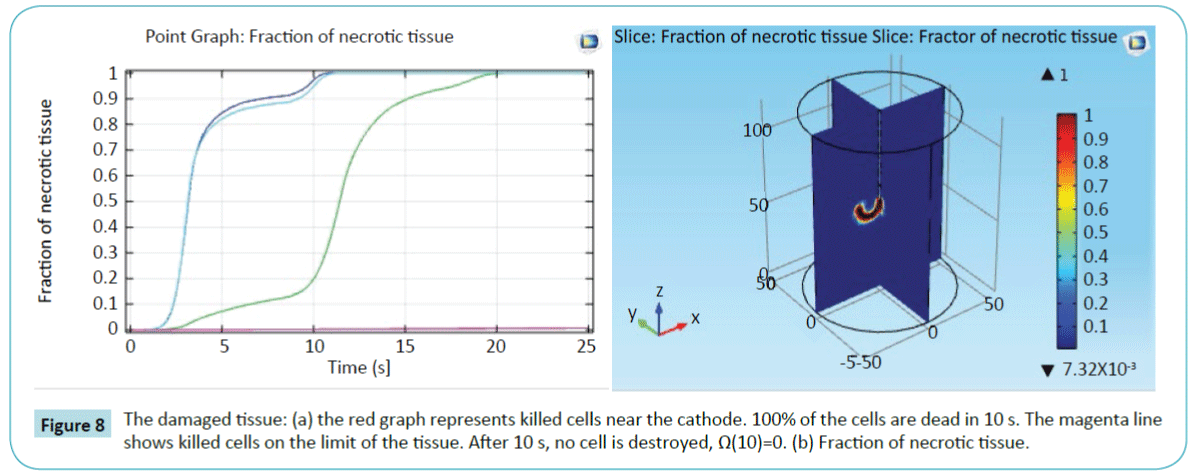
Figure 8: The damaged tissue: (a) the red graph represents killed cells near the cathode. 100% of the cells are dead in 10 s. The magenta line shows killed cells on the limit of the tissue. After 10 s, no cell is destroyed, Ω(10)=0. (b) Fraction of necrotic tissue.
To prove the efficiency of our model, we followed the temperature in several points by inserting probes at specific locations in our model. We chose a point A in the direction of the cathode and a symmetric point A' in the opposite direction. Figure 9 shows the temperature at different points. The temperature at the point in the opposite direction of the cathode is almost constant. However, the temperature increased in the direction of the cathode.
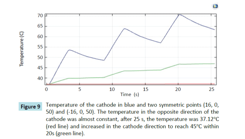
Figure 9: Temperature of the cathode in blue and two symmetric points (16, 0, 50) and (-16, 0, 50). The temperature in the opposite direction of the cathode was almost constant, after 25 s, the temperature was 37.12°C (red line) and increased in the cathode direction to reach 45°C within 20s (green line).
The control of the direction of the temperature diffusion offers a possibility to control the shape of the overheated zone. Other works explored many other parameters. The shape of the lesion depends on the number and the form of the probe. Supan et al. [24] obtained, with 4 electrodes, a mushroom-like shape. The average applied power was 16 W. In Stefaan et al. [27], the ablation zone produced by a bipolar 2×2 electrodes is a reproducible rectangular. The optimal applied power is 50 W for 10 minutes. The ablation of the whole volume is obtained by, first, activating the 2×2 electrodes, then switching to other electrodes. The shape of the lesion is omnidirectional. Our probe produces a shape following the direction of the cathode and offers the possibility to control the direction of the temperature diffusion, contrary to the other systems. A succession of 2 W pulses are used.
The numerical approach is used to plan the ablation process before the surgery. It serves to detect the optimal values of different parameters influencing the process to avoid the destruction of the healthy cells around the ablative zone, which is important to achieve a total ablation with less damage. The Amplitude and the number of pulses can vary following the tumor size and must be fixed before starting the ablation. During the ablation process, the Computed Tomography (CT) technique or Magnetic Resonance Imaging (MRI) can be used to localize the tumor and follow the destruction process
Conclusion
In this paper, we have proposed a curved cathode probe model to control the direction of the temperature diffusion during thermal therapy. COMSOL Multiphysics is used to simulate the model. We have evaluated the necrotic tissue to see the portion of killed cells. The results prove that the cells are deemed to be killed, by heating under Joule Effect, in the direction of the curved cathode. We have also investigated numerically the temperature behaviour during the thermal treatments process. These investigations show that the temperature increased in the cathode direction while remaining almost constant in the other directions. It is proved that the model has the capability to control the thermal direction during the treatment. By using our probe, the number of healthy cells killed is estimated to be very low. Our model results showed the expected behaviour of the temperature diffusion suited as thermal therapy protocol in biological tissues. The use of this model by oncologists or radiotherapists can minimize the tissue collateral damage and to help plan an efficient thermal therapeutic treatment. Future work will compare the numerical results obtained by simulation and real data from clinical experiments to validate our model. Other probe diameters can be explored and compared to detect the optimal diameter.
11099
References
- Anbar M (1998) Clinical thermal imaging today. IEEE Eng Med Biol 17: 25-33.
- Lay-EkuakilleA, VergalloP, Veneziano D, Conversano F(2014) Thermal image processing for accurate real time decision making in surgery. IEEE International Symposium on Medical Measurements and Applications (MeMeA).
- Ring EF, Ammer K (2012) Infrared thermal imaging in medicine. PhysiolMeas 33:33-46.
- Zhong-San D, Jing L (2004) Mathematical modeling of temperature mapping over skin surface and its implementation in thermal disease diagnostics. Computers in Biology and Medicine. September 34:495-521.
- Dariush S, Nicolae V (2011) Cancer Treatment with Hyperthermia. Current Cancer Treatment- Novel Beyond Conventional Approaches, Prof. OnerOzdemir (Edn.) ISBN: 978-953-307-397-2,
- Neufeld E, Pauildes M, Capstick M (2010) Recent Advances in Hyperthermia Cancer Treatment. Asia-Pacific International Symposium on Electromagnetic Compatibility 389-392.
- Payam H, Amir M, Khezry B (2015) Bioheat transfer analysis of biological tissues induced by laser irradiation. International Journal of Thermal Sciences 90:214-223.
- Huber PE, Jenne JW, Rastert R (2001) A new noninvasiveapproach in breast cancer therapy using magnetic resonance imaging-guided focused ultrasound. surgery 61:8441-8447.
- Harry HP (1948) Analysis of Tissue and Arterial Blood Temperatures in the Resting Human Forearm. Journal of Applied Physiology 1: 93-122.
- Matthew PC, Samara LF, Andrew N S (2012) Thermal Model for a Heated Neural Micro-Probe. Proceedings of the COMSOL Conference in Boston.
- Chen MM, Holmes KR (1980) Microvascular contributions in tissue heat transfer. Ann N Y AcadSci335: 137-150.
- Weinbaum S, Jiji LM, Lemons DE (1984) Theory and Experiment for the Effect of Vascular Microstructure on Surface Tissue Heat Transfer-Part I: Anatomical Foundation and Model Conceptualization. Journal of Biomechanical Engineering 106: 321-330.
- Arkin H, Xu LX, Holmes KR (1994) Recent Developments in Modeling Heat Transfer in Blood Perfused Tissue. IEEE Transactions on Biomedical Engineering44:97-107.
- BalusuK,Suganthi SS, Ramakrishnan S. Modelling Bio-heat transfer in Breast Cysts using Finite Element analysis. International Conference on Informatics, Electronics & Vision. May 2014 pp: 1-4.
- Xin C, Gerald MS(2009) Mathematical modeling of thermal ablation in tissue surrounding a large vessel. J of BiomechEngp: 131.
- Caleb KC(1992) Mathematical models of Bioheat transfer. Advances in heat transfer22:19-30.
- Pennes EW (1948) paper revisited. Journal of Applied Physiology Published 85:35-41.
- Murat T, Unal C, Cem P (2006)The bio-heat transfer equation and its applications in hyperthermia treatments. EngComput 23:451-63.
- Kolios MC, Worthington AE, Sherar MD, Hunt JW (1998) Experimental evaluation of two simple thermal models using transient temperature analysis. Physics in Medicine and Biology43: 3325-3340.
- Kok HP, Gellermann J (2013)Thermal modeling using discrete vasculature for thermal therapy: A review. Int J Hyperthermia29: 336-45.
- Zhong-San D, Jing L(2002) Monte Carlo method to solve multidimensional bioheat transfer problem. Int J of Computation and Methodology42:543-67.
- OhsumiS, Takashima S, Aogi K, Usuki H (2002) Prognostic value of thermographical findings in patients with primary breast cancer. Breast Cancer Res Treatment74: 213-20.
- Steketee J and Van-der-Hoeck MJ(1979) Thermal recovery of the skin after cooling. Phy Med Bio 24:583-7.
- Tungjitkusolmun S, Staelin ST (2002) Three-dimensional finite-element analyses for radio-frequency hepatic for ablation. IEEE Trans Biomed Eng49:3-9.
- Ruxsapong P, Phasukkit P, Tungjitkusolmun S, Prasantamrongsiri S, Sanpanich A (2013) Airflow analysis of radiofrequency ablation for asthma therapy by using 3D finite element method. Biomedical Engineering International Conference1-4.
- YhamyindeeP, PhasukkitP, Tungjitkusolmon S, Sanpanich A(2012) Analysis of heat sink effect in hepatic cancer treatment near arterial for microwave ablation by using finite element method. Biomedical Engineering International Conference1-5.
- Stefaan M, Yansheng J, Jacques J (2015) Bipolar radiofrequency ablation with 2 × 2 electrodes as a building block for matrix radiofrequency ablation: Ex vivo liver experiments and finite element method modeling. International Journal of Hyperthermia31:649-65.
- Kok H, Wust P, Stauffer P (2015) Current state of the art of regional hyperthermia treatment planning: a review. Radiation Oncology (London, England) 10:196
- Jalali A, Ayani MB, Baghban M( 2014) Simultaneous estimation of controllable parameters in a living tissue during thermal therapy. Journal of Thermal Biology 45:37-42.
- Szasz A and Vincze G (2006) Dose Concept of Oncological Hyperthermia: Heat-Equation Considering the Cell Destruction. Journal of Cancer Research and Therapeutics2:171-81.
- Dewhirst MW, Viglianti B L, Lora-Michiels M (2003) Basic principles of thermal dosimetry and thermal thresholds for tissue damage from hyperthermia, International Journal of Hyperthermia. 19:267-94.
- Vincze G, Szasz O and Szasz A (2015) Generalization of the Thermal Dose of Hyperthermia in Oncology. Journal of Biophysics5:97-114.
- Garcia PA, Rossmeisl JH, Neal RE (2011) A parametric study delineating irreversible electroporation from thermal damage based on a minimally invasive intracranial procedure. Biomed Eng Online10:34.
- Garcia PA, Davalos RV, Miklavcic D (2014) A Numerical Investigation of the Electric and Thermal Cell Kill Distributions in Electroporation-Based Therapies in Tissue. PLoS ONE 9: e103083.
- Dewey WC (1994) Arrhenius Relationships from the Molecule and Cell to the Clinic. International Journal of Hyperthermia 10:457-83.
- Panescu D, Whayne JG, Fleischman SD (1995) Three-dimensional finite element analysis of current density and temperature distributions during radio-frequency ablation. IEEE Transactions on Biomedical Engineering 42:879-90.
- Santis VD, Feliziani M, Maradei F and Buccella C (2009) Finite Element analysis of temperature increase in vascularized biological tissues exposed to RF sources. IEEE Trans. Magn45:1682-1685.
- Singh R, Das K, Okajima J (2015) Modeling skin cooling using optical windows and cryogens during laser induced hyperthermia in a multilayer vascularized tissue. ApplThermEng89:28-35.
- Xin C, Gerald MS (2010) Modeling of laser coagulation of tissue with MRI temperature monitoring. BiomechEng132:064503.