Keywords
Knee ankle foot orthosis; Stance control orthosis; Knee orthotic joint; Locking mechanism; Knee flexion; Knee extension
Introduction
Many individuals sustain quadriceps weakness or knee instability because of paralysis, spinal cord injury, or polio. They are usually prescribed KAFO, which provides knee stability and protects the knee from collapsing during the standing and stance phase of walking. KAFO keeps the knee locked in full extension throughout the gait cycle. Hence, knee flexion is prevented during the swing phase. Since KAFO resists free knee motion during swing phase thus individuals have to compensate it by an unnatural gait pattern. This compensatory gait pattern results in the hip hiking of the braced leg during the swing phase to attain sufficient foot-to-ground clearance, circumduction, and contralateral foot vaulting [1,2]. Walking with a locked knee leads to greater metabolic energy expenditure [3]. Traditional KAFOs also limit the ability of users to walk on irregular or inclined surfaces, ascend or descend stairs, and step over obstacles because of inadequate toe clearance. Moreover, long-time use of locked knee KAFO and walking with an abnormal gait may lead to pain and the joint disfunction of the hip and lower back [1].
Rehabilitation researcher could discern the need of an orthotic device that would allow knee flexion for obtaining free knee motion during swing phase and provide adequate knee stability for weight bearing during stance phase of gait cycle. Extensive measures were implemented in the last three decades to develop such type of KAFO [4]. Numerous prototypes were designed, fabricated, and tested. Typically these orthotic devices are referred as Stance Control Orthosis (SCO). These orthotic devices are also called stance control knee–ankle–foot orthosis (SCKAFO) since these devices were developed from KAFO. SCAFOs are designed to lock automatically the knee joint that resists knee flexion during the stance phase and provides sufficient stability to support body weight. The knee actuation mechanism automatically unlocks the knee during the swing phase to allow free knee motion. Therefore, SCKAFO allows a more normal gait and greater cosmetic acceptance compared with the traditional fixed-knee KAFO [5]. SCKAFO also improves gait efficiency, kinematics, and mobility. Another significant benefit is the reduction of the metallic energy expenditure of the user [6,7].
Numerous mechanisms and design approaches have been used to develop stance control knee mechanism integrated with the traditional structural KAFO. Some of these mechanisms and approaches are ratchet or pawl [8], eccentric cam locking system [9], inner pendulum mechanism [10], wrap spring clutch [11], belt clamping [4], dual stiffness mechanism [12], hydraulic [13], electrical motor controlled actuation [14], electromechanical controlled [15], hybrid neuroprosthesis [16], gas spring cylinder actuated [17] and Swiss-Lock actuated [18] system. Some of these approaches lack a smooth switching operation between the stance and swing phase, and most are heavy, bulky, and lacking in cosmetic qualities. The purpose of this article is to evaluate and compare the existing designs and determine the possible design challenges for a new SCKAFO.
Usefulness of SCO over Traditional KAFO
Typically the patients suffering from significant lower limb muscle weakness are recommended to use a KAFO. Basically, these KAFOs are having a hinge knee joint mechanism that provides knee stability for weight bearing by locking knee joint and resisting knee flexion during stance phase. But it also locks the knee and prevents free knee motion also in swing phase that leads to an unnatural gait pattern. Therefore, when a patient ambulates with KAFO and moves his leg forward he has to experience hip hiking in swing phase. In addition redeeming gait pattern comprises foot vaulting, lateral shake or oscillation of upper body and leg motility. Resisting knee flexion during swing phase causes sudden initial loading in stance phase and hinders balanced forward movement of center of mass of the user [19]. According to Waters et al. fixed knee motion can reduce 23-33% of gait efficiency of a patient and elevate center of mass position 65% vertically [7]. Unnatural gait pattern causes soft tissue, hip and knee joint dis-function and motion loss. It leads toward increase in lower limb muscular effort and elevate the energy expenditure during walking [1]. Since, flexed knee actively make shorter the leg in swing phase, thus, free knee motion increases the cadence. It allows the users to walk with more similar to normal gait pattern. Knee flexion is also very essential during stair climbing or slant and ambulation on inclined surface. There is great possibility of stumble with fully extended knee, since, KAFOs resists the leg flex to prevent fall. Hence, the stance control KAFO is a solution in this case, because it allows free knee motion during swing phase and resists knee flexion during stance phase for preventing knee collapse and to support weight bearing [19]. In addition some studies recommended- since stance control orthosis allows free knee motion during swing phase it improves walking efficiency and kinematics with compare to typical KAFO.
Irby et al. [20] demonstrated a report analyzing results of 14 patients using Dynamic Knee Brace System. The Dynamic Knee Brace System was a stance control orthosis and they had been using it for 6 month which was an open enrolment clinical trial. Among those 14 patients seven were novice user and seven were experienced with traditional KAFO. The result exhibited significant enhancement of knee flexion and peak hip flexion for both types of patients. Walking velocity and stride length of novice users were increased substantially.
Lehmann et al. [21] investigated the rate of oxygen consumption and energy cost while using stance control orthosis. He observed the oxygen consumption and metabolic energy expenditure of two spinal cord injury patients and two non-disable subjects during ambulation. Substantial reduction in energy requirement and oxygen consumption was observed for two no-disable subject. Since, the two spinal cord injury patients were suffering acute lower limb muscular weakness to flex their leg during swing phase, hence, little improvement was observed for them. Kaufman et al. [22] also investigated the rate of oxygen consumption for SCKAFO users. His study provided a result for those patients suffered from extremity of lower limb paralysis. The study showed a significant reduction in metabolic energy cost for SCKAFO users and an oxygen consumption difference of 1 mL/kg/mm between traditional KAFOs and SCO users.
Zessimopoulos et al. [23] investigated on biomechanical kinematics and energetic effect on non-disable subjects using SCKAFO. The study recommended SCO for the patients of lower limb extremity since it allows users to walk more similar with natural gait. It also showed analytical comparisons walking with locked knee mode, free knee motion and stance control mode. Free knee motion and stance control mode exhibited comparatively similar result with respect to locked knee mode. Study results showed a significant reduction in hip hiking and circumduction during swing phase. But the study did not find any significant difference in oxygen cost compared with stance control mode and locked knee mode. In general, the study demonstrated improvement in gait kinematics and enhancement of knee stability during weight bearing. It also revealed the traditional KAFO increases possibilities of stumbling walking, quadriceps weakness on the affected side and become troublesome during stair ascending and descending. McMillan et al. [1] demonstrated a study on three lower limb weakness extremity patients using SCKAFO of Harton Technology Inc. The study reported lower heart rate and improvement in gait kinematics like, increased mobility, faster gait and longer steps. The gait patterns of those subjects were more similar to normal gait as well.
Orthosis with Electromechanical Actuation and Control System
Irby’s dynamic Knee Brace system
Dynamic Knee Brace System (DKBS) by Irby et al. [11] is a stance control knee orthotic joint. The locking system utilizes an electronically controlled clutch and brake mechanism. The device comprises a conventional unidirectional wrap spring clutch, pressure sensors, kinematic sensors, and a microprocessorbased control unit. All these parts are fitted with a conventional KAFO (Figure 1). Pressure sensors below the foot sense the contact between foot and ground. The kinematic sensors sense the movement of knee. The microprocessor-based control unit monitors the input signals from sensors. A control algorithm inside the control unit generates the joint actuation commands. These commands then actuate a solenoid, which locks and unlocks the wrap spring clutch [5,11].
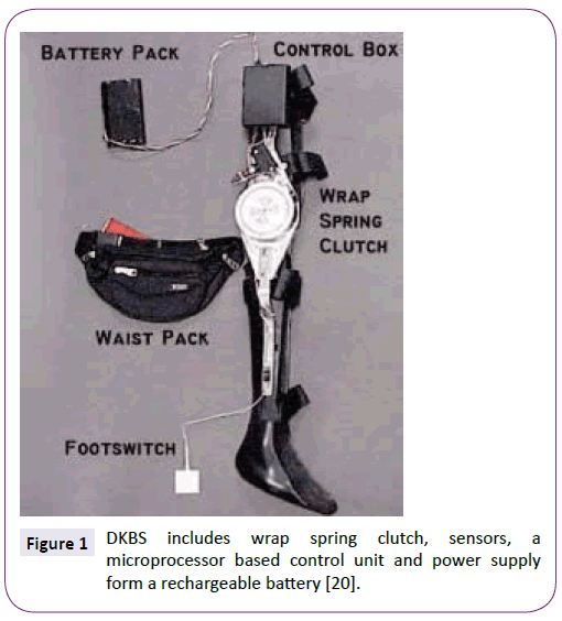
Figure 1: DKBS includes wrap spring clutch, sensors, a microprocessor based control unit and power supply form a rechargeable battery [20].
The wrap spring clutches typically permit torque transmission from one shaft to another in a definite rotational direction. DKBS consists of an input shaft, an output shaft, and a helical spring. These two shafts have a common rotational axis. The input shaft is attached with an input hub, and the output shaft is attached with an output hub. Both of input and output hubs are engaged with a helical spring, which acts as a self-engaging brake between them. When torque is applied to the input hub in a counter clockwise direction, the helical spring fastens firmly on the adjacent input and output shafts. It locks the knee joint. Conversely, when torque is applied in a clockwise direction, the spring unfastens from the adjacent input and output shafts and allows the free knee motion [24-29].
Advantages and drawbacks
• It is easily attachable with conventional KAFO.
• Weight of the DKBS is approximately 1.1 kg and including KAFO it is about 3 kg [20].
• DKBS can withstand a valgus load of 100 Nm and transverse or axial moment load of 35 Nm.
• A bit bulky and some users find it difficult to wear.
Sensor walk
Sensor Walk was developed by Otto Bock in conjunction with the Mayo Clinic. It is a recent modification of the Otto Bock Free Walk. The sensors in the footplate can electronically assess the relative orientation of the wearer’s limb and determine the appropriate time to engage or disengage the knee joint through the microprocessor. Wrap spring clutch operation is used for locking system. No extension moment is required to unlock the joint. Therefore, the device helps the patient attain a more natural gait. The device is powered by a lithium-ion battery, which powers the device for approximately 15,000 steps [30].
Advantages
• The device provides additional stability through the flexionblocking mechanism to prevent stumbling. This mechanism can be activated any time when necessary throughout the gait cycle.
• It is suitable for patients with weight up to 136 kg and knee flexion contracture of 15°.
• It is able to function in three modes: locked joint mode, SCO mode and free swing mode.
• Commercially available and user friendly.
Becker orthopaedic E-Knee
E-Knee basically consists of a foot plate, control circuit unit, and magnetically-activated locking mechanism. Pressure sensors are attached beneath the foot plate, detect the heel strike and toe off. The control circuit unit obtains the input signal from these sensors and actuates the locking operation automatically. In the mechanical part of the locking mechanism there is a single direction dog clutch. It is magnetically activated and consists of two circular shaped ratchet plates. These ratchet plates are spring biased and separated. One plate is placed inside an electromagnetic coil. This coil becomes energized when pressure sensors of foot plate sense pressure during heel strike. The energized electromagnetic coil forces both of the ratchet plates to be engaged and resist knee flexion [31,32]. During toe off the control system de-energizes the electromagnetic coil and unlocks the knee joint to allow free knee motion. The device is powered by a lithium ion battery [33].
Advantages and drawbacks
• Commercially available.
• Device battery is able to provide power continuously for a day long and can be recharged within four to six hours [33].
• It is not suitable for patients weigh more than 100 kg or with more than 15° fixed valgus deformation at the knee.
• It is a bit bulky and heavy because of its electromagnetic coil.
• The device is slightly noisy because of the clicking sound of locking operation.
Servo motor powered SCO
Kim et al. [15] developed an electromechanical KAFO for Korean poliomyelitis. It is compact in design. The main structural body of the KAFO is made of aluminium and the AFO part is fabricated with plastic. The orthotic device has four functional parts – a plastic AFO part with sensors, a knee joint servo motor controller, a power circuit and a motor controller circuit. In the knee joint a wrap spring clutch, PSI-5, is used (Figure 2). The clutch mechanism is governed by a servo motor. The motor controller collects input from AFO sensors. The sensors are attached at heel and metatarsal heads for detecting heel contact, full stance and toe off. The servo motor locks the clutch during heel contact. The clutch remains locked until the end of the stance. The servo motor releases the clutch when the sensors of the metatarsals detect the beginning of the swing phase. The main control circuit is powered by +5 V DC. A rechargeable Ni-MH battery (+3 V DC and 2,400 mA) powers the knee joint servo motor.
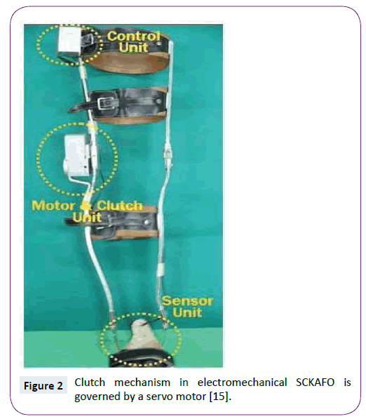
Figure 2: Clutch mechanism in electromechanical SCKAFO is governed by a servo motor [15].
Advantages and drawbacks
• It is lighter, overall weight is only 1.52 kg.
• It can produce higher flexion resistance moment, about 28 Nm.
• No need of external knee extension moment for proper locking operation.
• Energy consumption test revealed lower metabolic energy consumption of users.
• Commercially still not available.
Gas spring cylinder controlled SCO
A SCO with 2° freedom was designed and developed by Kang et al. [17]. A solenoid guided gas spring cylinder was used to control knee motion in different phases of gait cycle. Air muscle was employed for increasing the stability and strength of hip joint. The cylinder operation is regulated by a solenoid driven stopper to allow the free knee motion during swing phase and lock the knee joint during stance phase. A control system was also developed to control the orthotic device. In the control system there is a solenoid, a lithium ion rechargeable battery, an air pump and a controller. The micro-processor in the controller collects signals from the electromyogram and force sensors attached to the knee and foot.
The solenoid driven gas spring cylinder and stopper are the main functional components of the system. The cylinder and solenoid are attached to a metal structural body. The force sensors sense no ground reaction force during the swing phase and the solenoid get turned on. It moves the stopper outward direction to unlock the knee joint. When the heel touches the ground, the force sensors begin to sense ground reaction force. The gas spring cylinder restores the retained elastic energy to help knee extension. The solenoid is also move inward the stopper and turned off when the knee joint straightens fully (Figure 3). Now stopper resists movement of gas spring cylinder, and locks the knee joint.
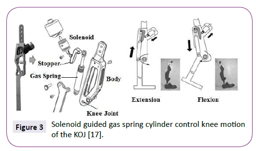
Figure 3: Solenoid guided gas spring cylinder control knee motion of the KOJ [17].
Advantages and drawbacks
• In performance test, the device showed a faster gait by increasing walking velocity by 16%, 31 ± 2 cm/s; which is 26 ± 2 cm/s for typical powered gait orthosis (PGO). It also shortens the duration of stance phase (70% instead of 74%) and enhanced the stance phase (30% instead of 26%) which is closer to natural gait.
• Still commercially not available.
Electrical DC motor controlled SCO
Font–Llagunes et al. [14,34] developed a DC motor controlled actuator to control knee joint motion during gait. A klenzak ankle joint, plantar sensors and optical encoders were used in the prototype. A fractional order controller is employed to control the entire orthotic device. The actuator, sensors, and control system are powered externally. The device is locked mechanically to ensure safety in case of a power failure.
A DC motor is mounted onto the lateral sides of the knee to control knee flexion and extension during the swing phase. A spring-loaded pawl locking system is adopted to lock the knee and resist knee motion during the stance phase. The locking system is mechanically operated and does not require any power to be mounted at the medial side. Four contact planter sensors are attached to the sole of each unit in the ankle section to sense the different phases of the gait cycle and to resist dorsiflexion at a specific ankle angle. An optical encoder is enclosed at the ankle joint to calculate joint angular velocity, which would be sent to the controller. The foot sensors monitor the initial foot contact and solenoid inside the locking system locks the knee joint. The DC motor at knee joint doesn’t produce any torque to exert upon the orthotic joint at this phase. At the beginning of the swing phase the planter sensors can detect no foot contact, the plunger inside the locking system is pushed by solenoid and the knee joint becomes unlocked. Hence, the motor controlled knee actuator supports knee flexion and extension. The controller controls the motor rotation based on data input from optical encoder. The entire function is subsequently repeated at the end of the swing phase once the sensors detect new heel contact (Figure 4).
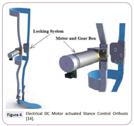
Figure 4: Electrical DC Motor actuated Stance Control Orthosis [14].
Advantages and drawbacks
• The orthotic device is suitable for different patients and is not bulky (1.9 kg in weight).
• Two autonomous knee joint mechanisms control the knee motion at the swing and stance phase.
• The device is able to exert a torque of 15 Nm during the swing phase.
Robotic knee orthosis (RKO)
The elementary structural body of this orthotic device is fabricated with carbon fibre. RKO involves three different active functions, including ambulating, stair ascent or slant-oriented walking, and sitting-to-standing movement. The control panel and most of the functional elements are housed in the upright part of the orthosis. The main functional elements of the RKO include the KOJ actuator, actuator motion control motor, sensors that measure the knee joint angle, pressure sensors at the foot, and a lithium-ion battery that supplies power (Figure 5). A number of sensors also control the actuator motor current and voltage, measure the inner temperature of the actuator, and control the rechargeable battery voltage.
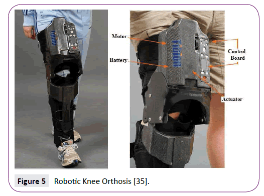
Figure 5: Robotic Knee Orthosis [35].
A RKO typically receives signal inputs from foot pressure and knee angle sensors and exerts force accordingly. The foot sensors detects the phase of the gait cycle and time duration for supporting patient weight during the stance phase. The knee angle sensors detect the knee motion and torque sensors ascertain the amount of torque need to be exerted by the actuator. A drive train coupling is located between the outer end of the KOJ actuator and the orthosis. The actuator is coupled with the drive train coupling during the stance phase and produces adequate knee joint extension torque to support weight bearing. The variable ratio of the drive train coupling modulates the amount of torque and is based on the torque requirement monitoring sensors. A pre-programmed control system controls the actuation system. The control system includes the actuator control circuit, power circuit, and battery charging circuit. The power circuit is able to switch between AC and DC power [35,36].
Adventages and drawbacks:
`• An RKO is not so bulky, approximately 3.7 kg in weight.
• To be a user convenient orthosis the RKO has a user control panel board.
• The device can be configured by limiting walking speed and torque generation.
• The sit-to-stand function is governed by a manual mode of operation [35,36].
• The functional test revealed that the orthosis exhibits approximately 17% enhancement in walking velocity [36]. The orthosis also augments step length with training [37].
Microcomputer controlled SCO
Nakanishi et al. [18] and his group developed a microcomputer controlled stance control system which is more simplified in terms of structure and control system, easier to control, compact and light. The elementary structural body is made of carbon fibre reinforced composite material. The instrumental design of the device is also very simple. Only two pressure sensors detect the gait phases and provide input to the microcomputer. One pressure sensor was embedded at the heel and another at metatarsal joint. For controlling the knee motion in swing and stance phase a commercially available Swiss-lock KOJ was used. A motor is employed to operate a lever that locks and unlocks the knee-locking system. The motor operation is controlled by the microcomputer (Figure 6).
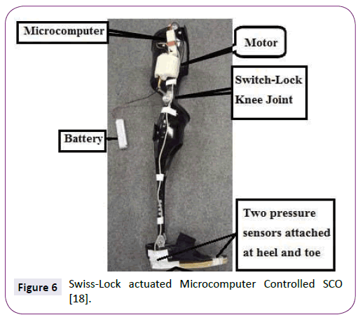
Figure 6: Swiss-Lock actuated Microcomputer Controlled SCO [18].
The weight of the microcomputer is only 140 gm. The pressure sensor below the heel detects the initial contact during the earlier part of the stance phase. The microcomputer switches off the Swiss-lock knee joint. The Swiss-lock knee joint keeps the knee extended, resists knee flexion, and supports the body weight at off mode. The knee joint remains locked during midstance when two pressure sensors are on and at the end of the stance phase when the metatarsal sensor is on. When both of the pressure sensors are off at the beginning of the swing phase, the microcomputer switches on the Swiss-lock knee joint by operating the lever motor. The motor pulls up the lever and unlocks the KOJ to allow knee flexion and free knee motion. AA batteries are utilized as a power supply.
Adventages and drawbacks:
• The overall weight including batteries and KAFO is less than 1.3 Kg.
• The overall design and function is very simple. Easier to control, compact and light.
Stance control knee mechanism with hybrid neuroprosthesis
Hybrid neuroprosthesis (HNP) combines mechanical orthosis and functional neuromuscular stimulation. HNP overcomes limitations and allows bracing or functional neuromuscular stimulation (FNS) to generate an effective intervention. The HNP approach divides walking into two main functional tasks: body weight support (accomplished by bracing) and limb and body propulsion (accomplished by FNS). A sensor-based controller modulates the amount of stimulation provided to the knee extensor muscles, which are synchronized with the state of stance control knee mechanism (SCKM). The controller minimizes the amount of stimulation required to extend the knee during FNS-induced swing in preparation for the heel strike and during stance when knee support against collapse is provided by SCKM. The function of SCKM is to lock the knee during stance and unlock it during swing to provide free knee flexion.
SCKM is a hydraulic mechanism that incorporates a double-flow cylinder (Figure 7) with a 9/16 in bore, 0.25 in rod diameter, and 3 in stroke and is rated at the maximum operating pressure of 2000 psi. The knee joint is locked by the closing operation of a double-way solenoid valve during the standing and stance phase of the gait cycle. A miniature single-acting cylinder with spring return is incorporated into the system to act as a fluid accumulator. The device is designed to lock the knee as a safety measure and aims to resist knee flexion and prevent collapse, allowing extension and maintaining upright stance. Such can be achieved by specifying a valve cracking pressure that is low enough to be easily be increased by applying a small extension moment with FNS. The cylinder is attached by a spherical rod eye and clevis joints to the upper thigh and leg, respectively, to convert the linear movement of the piston of the cylinder to the rotary movement of the knee. SCKM resisted up to 70 Nm of torque when fully extended in bench testing. The value is well above what is normally observed during gait. Thus, the mechanism is capable of providing support when stimulation is turned off during stance. SCKM reliably unlocks within 200 milliseconds with knee flexion torque of up to or below 50 Nm and in 12 milliseconds when unloaded. The passive resistance is less than 2 Nm. The compliance of the mechanism is observed at augmentation from 2° to 5° of knee flexion [16,38].
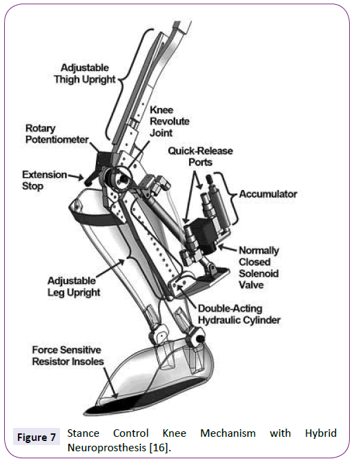
Figure 7: Stance Control Knee Mechanism with Hybrid Neuroprosthesis [16].
Advantages and drawbacks:
• The FNS subsystem provides the power to move forward the lower limbs and the body during walking. Hence it is compatible enough for the patients of acute muscle weakness.
• This device is bulky and the overall design is a bit complex.
Discussion
Design criteria
SCKAFOs are distinct from all other conventional KAFOs forasmuch remarkable attribute of allowing free knee motion during swing phase but provide knee stability during stance phase for weight bearing. The prime and basic functions of SCKAFOs are to keep the knee stiff enough by locking the knee joint during stance phase and provide free knee flexion and extension during swing phase. SCKAFOs either mechanically controlled or electromechanically satisfy the prime criteria. A number of additional design criteria should also be fulfilled to develop a SCKAFO that is competent enough with more beneficial features.
-For stair climbing or slant and to recover from stumble the device should capable to resist knee flexion and keep it rigid at any knee or ankle angle during stance phase.
-For permitting the user to seat and stair climbing or slant the device should allow the motion at any knee or ankle angle while it can sense limb unloading.
-The device should comprise smooth and quick switching system between stance and swing modes. The reaction time should be less than 6 milliseconds.
-For smooth forward movement of body centre of mass (COM) the design of a device should include controlled knee flexion at stance phase.
-The device should be noise free.
-The device should be light and cosmetic in appearance. The overall weight should not be more than 2.5 kg.
-The device should be less bulky.
-Design complexity should be eliminated for easy manufacturing and to minimize cost.
Future Direction
Extensive improvement has been carried out in last few decades to design and develop orthosis competitive for various impaired patient, however, several design challenges remain. An ideal SCKAFO should reluctant from limitations. A number of factors limit current commercial designs. If these limitations can be overcome day by day, the number of users will be increased significantly. The rate of rejection will be minimized as well. A proper design can also enhance the ease of mobility, level of user confidence and security. Better three dimensional human gait model analysis can assist for better realization of musculoskeletal morphology of lower limb locomotion and neural function. That could leads to a low-mass orthotic design [39].
Smooth and quick switching system between stance and swing phase mode is a remarkable challenge till now. Because, fully extended knee is required for generating knee extension moment to lock the knee joint of some SCKAFOs. Consequently these SCKAFOs cannot provide adequate support for body weight during stair climb or slant and unable to prevent stumbling.
Many SCKAFOs are heavy, complicated in shape and considerably noisy. These are very important design challenges since it can reduce rate of rejection significantly. Additional modification is required to make SCKAFOs more cosmetic, lighter, and noise free. Lighter composite material like carbon fibre plastic can be used for main structural element. Noise can be minimized by avoiding metal to metal contact in design. High stress development inside the KOJ inner element is also an important issue, since, durability and life time is another important design challenge. During stance phase large amount forces develop into tiny elements having smaller area. Hence, force should be distributed at low concentrations to reduce stress. Material development of higher rigidity to weight can be a solution for this problem.
Optimization of electrical power consumption of entire device is also a design challenge. A small and compact control system with advanced DC power battery technology can be a solution. A good sensor system that can precisely detect the gait phases is another important challenge. Many sensors fail to work properly because of moisture and dust; thus, suitable protection should be developed to eliminate the trouble caused by ambient dust or moisture.
Conclusion
Impaired individuals with lower limb muscle weakness are very often prescribed to use KAFO for supporting the user body weight during walking and standing. Since KAFOs resist free knee motion during swing phase and compel to walk with an abnormal gait pattern the rejection rate is about 58% to 79% [22,40]. SCKFOs are a good alternative as they are designed to allow free knee motion during the swing phase while providing knee stability for weight bearing during the stance phase. SCKAFOs facilitate ambulation with a more natural gait. However, the success of commercially viable SCKAFO designs is limited because of the weight, bulkiness, lack of enough cosmetic appeal, noise, and cost. In addition creation of a compact and less bulky design is limited by the high stress formation in the inner elements of the device while supporting the body weight of the user during the stance phase [41,42]. Design optimization is also be smeared for obtaining a smooth switching between stance phase and swing phase. Greater user acceptance and lower rejection rate of a SCKAFO design may be achieved by overcoming the design challenges like better performance, user security, compact size, lighter weight, reduced noise and functional improvement.
Acknowledgment
This research is supported by UM High Impact Research Grant (UM.C/HIR/MOHE/ENG/28 and UM.C/HIR/MOHE/ENG/10) from University of Malaya, Malaysia.
Conflict of Interest
The authors declare that there is no conflict of interests regarding the publication of this article.
7892
References
- McMillan AG, Kendrick K, Michael JW, Aronson J,Horton GW (2004) “Preliminary evidence for effectiveness of a stance control orthosis”, Journal of Prosthetics and Orthotics 16: 6-13.
- Kerrigan DC, Frates EP, Rogan S, Riley PO (2000) Hip hiking and circumduction: quantitative definitions. Am J Phys Med Rehabil 79: 247-252.
- Mattsson E, Broström LA (1990) The increase in energy cost of walking with an immobilized knee or an unstable ankle. Scand J Rehabil Med 22: 51-53.
- Yakimovich T, Kofman J, Lemaire ED (2006) Design and evaluation of a stance-control knee-ankle-foot orthosis knee joint. IEEE Trans Neural Syst Rehabil Eng 14: 361-369.
- Irby SE, Bernhardt KA, Kaufman KR (2005) Gait of stance control orthosis users: the dynamic knee brace system. Prosthet Orthot Int 29: 269-282.
- Irby SE, Kaufman KR, Mathewson JW, Sutherland DH (1999) Automatic control design for a dynamic knee-brace system. IEEE Trans Rehabil Eng 7: 135-139.
- Waters RL, Campbell J, Thomas L, Hugos L, Davis P (1982) Energy costs of walking in lower-extremity plaster casts. J Bone Joint Surg Am 64: 896-899.
- Leederdam NV, Kunst E (1999)“New UTX-swing orthosis: Normal gait and safe standing”, Orthopadie Technik 50: 506-515.
- Hatton BJ, Hatton DL, Wallace ZG (2003) “Articulating knee supports”, U.S. Patent No. 6,635,024.
- Nijenbanning G, Goudsmit JA (2005) “Gravity operated locking hinge”, U.S. Patent No. 6,979,304.
- Irby SE, Kaufman KR (2004) “Electromechanical joint control device with wrap spring clutch”, U.S. Patent No. 6,834,752 In Washington DC.
- Cullell A, Moreno JC, Rocon E, Cordero AF, Pons JL (2009) “Biologically based design of an actuator system for a knee-ankle-foot orthosis”, Mechanism and Machine Theorym 44: 860-872.
- Lemaire ED, Goudreau L, Yakimovich T, Kofman J (2009) “Angular-Velocity Control Approach for Stance-Control Orthoses”, IEEE Transactions on Neural Systems and Rehabilitation Engineering 17: 497-503.
- Font-Llagunes JM, Pàmies-Vilà R, Alonso J, Lugrís U (2011) “Simulation and design of an active orthosis for an incomplete spinal cord injured subject”, Procedia IUTAM 2: 68-81.
- Hwang S, Kang S, Cho K, Kim Y (2008) “Biomechanical effect of electromechanical knee-ankle-foot-orthosis on knee joint control in patients with poliomyelitis”, Medical & Biological Engineering & Computing 46: 541-549.
- To CS, Kobetic R, Bulea TC, Audu ML, Schnellenberger JR, et al. (2011) “Stance control knee mechanism for lower-limb support in hybrid neuroprosthesis”, Journal of Rehabilitation Research & Development 48:839-850.
- Kim G, Kang S, Kang S, Ryu J, Mun M, et al. (2009) “Unlockable knee joint mechanism for powered gait orthosis”, International Journal of Precision Engineering and Manufacturing 10: 83-89.
- Nakanishi Y, Kato N, Wada F, Hachisuka K, Watanabe Y, et al. (2012) “Development of a simple stance-control system for persons with poliomyelitis and an associated gait analysis”, In International Conference on Complex Medical Engineering.
- Yakimovich T, Lemaire ED, Kofman J (2009) Engineering design review of stance-control knee-ankle-foot orthoses. J Rehabil Res Dev 46: 257-267.
- Irby SE, Bernhardt KA, Kaufman KR (2007) Gait changes over time in stance control orthosis users. Prosthet Orthot Int 31: 353-361.
- Lehmann JF, Stonebridge JB (1978) Knee lock device for knee ankle orthoses for spinal cord injured patients: an evaluation. Arch Phys Med Rehabil 59: 207-211.
- Kaufman KR, Irby SE, Mathewson JW, Wirta RW, Sutherland DH (1996) “Energy-efficient knee-ankle-foot orthosis: A case study”, Journal of Prosthetics and Orthotics 8: 79-85.
- Zissimopoulos A, Fatone S, Gard SA (2007) Biomechanical and energetic effects of a stance-control orthotic knee joint. J Rehabil Res Dev 44: 503-513.
- Leerdam NGV (1993) “The swinging UTX orthosis, biomedical fundamentals and conceptual design”, University of Twente: Enschede, The Netherlands 57-65.
- Shlomovitz, Tal, Ronny Shelly (2008) “Knee-ankle-foot orthotic device." U.S. Patent 7,462,159.
- Travolta R (2002) “Stance control revolutionizes knee bracing”, Biomechanics 10: 53-62.
- Yakimovich T, Lemaire ED, Kofman J (2006) Preliminary kinematic evaluation of a new stance-control knee-ankle-foot orthosis. Clin Biomech (Bristol, Avon) 21: 1081-1089.
- Moreno J, Brunetti F, Rocon E, Pons J (2008) “Immediate effects of a controllable knee ankle foot orthosis for functional compensation of gait in patients with proximal leg weakness”, Medical & Biological Engineering & Computing 46: 43-53.
- Baydal JM, Barberà R, Belda JM, Poveda R, Durá JV, et al. (2006) “Performance validation of an innovative orthotic knee joint based on an optimal four bar linkage”, Journal of Biomechanics 39: S72-S72.
- Ottobock Orthopedic Services (2009) O.B. HealthCare, Sensor Walk White Paper 2-5.
- Naft JM, Newman WS (2003) “Orthosis knee joint”, U.S. Patent No. 6,517,503.
- Naft JM, Newman WS (2004) “Orthosis knee joint”, U.S. Patnent No. 6,770,045.
- Gary G. Bedard, Becker Orthopedic, Stance control Overview Guide II 8-17
- Font Llagunes JM, Romero F, HosseinNia S, Alonso FJ, Vinagre BM (2012) “A powered lower limb orthosis to assist the gait of incomplete spinal cord injured patients”, In XXIX Congreso Anual de la Sociedad Española de Ingeniería Biomédica.
- Horst RW (2009) A bio-robotic leg orthosis for rehabilitation and mobility enhancement. Conf Proc IEEE Eng Med Biol Soc 2009: 5030-5033.
- Wong CK, Bishop L, Stein J (2012) A wearable robotic knee orthosis for gait training: a case-series of hemiparetic stroke survivors. Prosthet Orthot Int 36: 113-120.
- Byl NN (2012) Mobility training using a bionic knee orthosis in patients in a post-stroke chronic state: a case series. J Med Case Rep 6: 216.
- To CS, Kobetic R, Bulea TC, Audu ML, Schnellenberger JR, et al. (2012) “Sensor-Based Stance Control With Orthosis and Functional Neuromuscular Stimulation for Walking After Spinal Cord Injury”, Journal of Prosthetics and Orthotics 24: 124-132.
- Lobet S, Detrembleur C, Massaad F, Hermans C (2013) Three-dimensional gait analysis can shed new light on walking in patients with haemophilia. ScientificWorldJournal: 284358.
- Bernhardt KA, Irby SE, Kaufman KR (2006) Consumer opinions of a stance control knee orthosis.Prosthet Orthot Int 30: 246-256.
- Rakib MI, Choudhury IA, Hussain S, Osman NAA (2015) Design and biomechanical performance analysis of a user-friendly orthotic device. Materials & Design 65: 716-725.
- Rakib MI, Choudhury IA, Osman NAA (2014) Development of a Prefabricated and User Friendly Stance-Control Orthosis. In 2014 3rd International Conference on Environment Energy and Biotechnology 70: 80-83.